Build Mode
Parts nobody makes anymore
Paired with your Bambu Lab A1 mini, this is a plain-language field manual for taking a hard-to-find classic-car part from reference to model to print to test fit, trim, clips, knobs, brackets, and jigs. The small stuff that keeps a restoration moving.
“I’ve been restoring some of my classic cars — it’s a very different kind of build mode.”
— Darren O’Meara
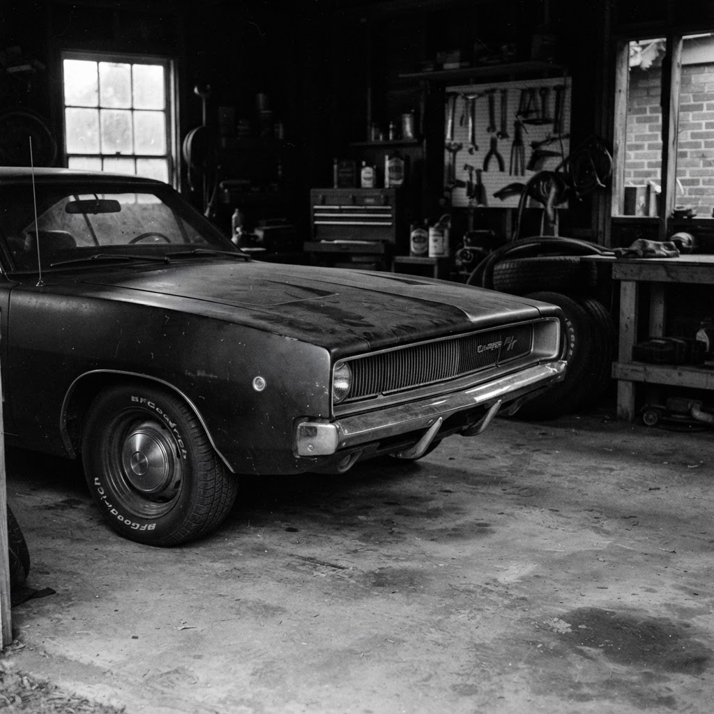
You’ve spent a career in one kind of build mode — shipping systems, scaling teams, sweating the details that don’t show but decide everything. This is that same instinct, now pointed at a workbench and a pile of parts that haven’t been manufactured in decades.
The A1 mini won’t rebuild an engine. What it will do is quietly solve the thousand small problems a restoration throws at you: the cracked vent tab, the missing knob, the clip that’s been discontinued since the Carter administration. Measure it, model it, print it, test the fit. Repeat until it’s right.
This manual is here to make that loop feel obvious. Welcome to the new build mode.
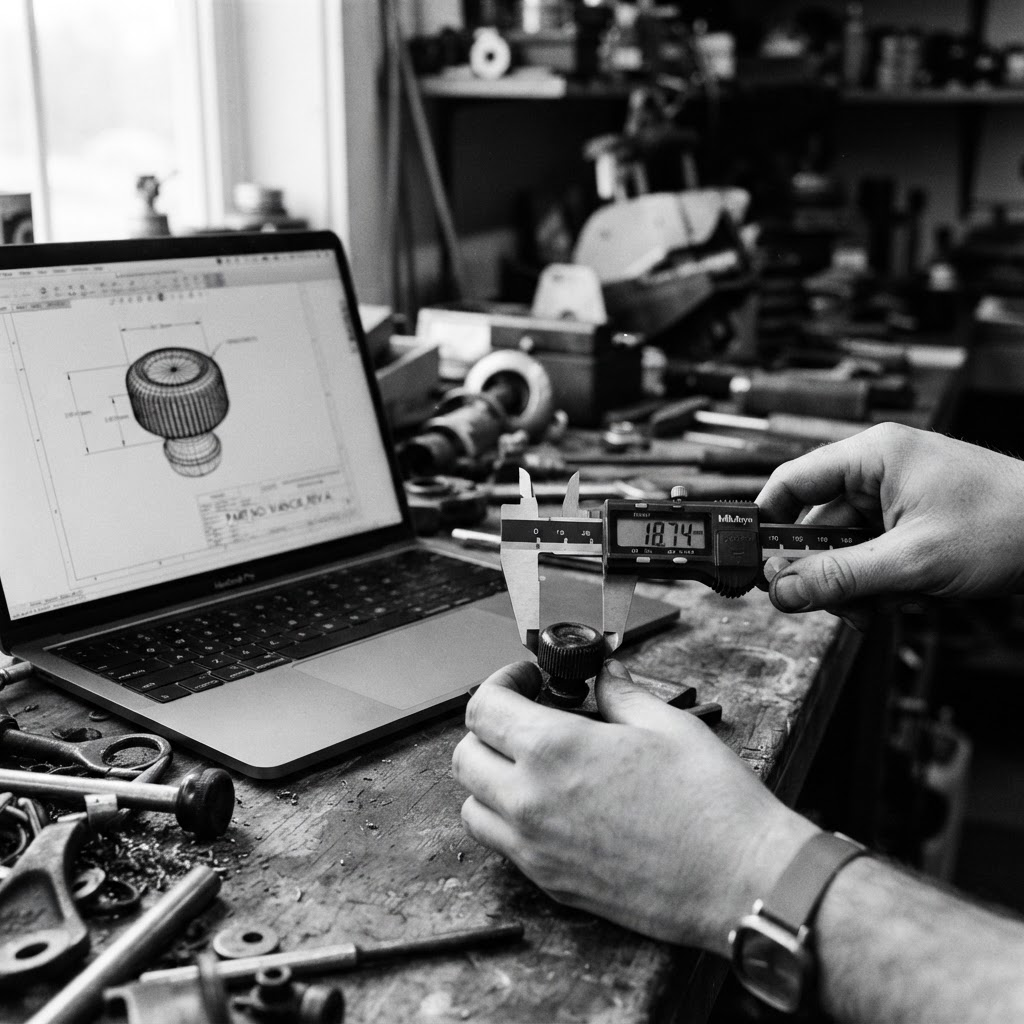
Reference. Model. Print. Test. Refine.
The same loop every time. Follow it in order — the test-coupon step is what separates a part that fits from a drawer of near-misses.
 01
01Reference
Measure the original with calipers. Record every dimension in millimeters — especially where it clips, slots, or screws in.
 02
02Model
Draw it in CAD or start from a known-good file. Keep walls at 3+ perimeters and avoid unsupported pins under 2 mm.
 03
03Print
Slice in Bambu Studio with the matching filament preset. Start from a 0.20 mm profile and preview every layer.
 04
04Test
Print a small coupon of just the mating feature first. Dry-fit cold, check with calipers, confirm the clearance.
 05
05Refine
Adjust one variable, reprint, finish, and install. Repeat the loop until it fits and looks like it belongs.
Material guidance
PETG recommended for small non-structural restoration parts, trim, clips, knobs, brackets, jigs, and prototypes.
Read moreTolerance / testing
Start tight, test often. Aim for a slight interference fit, then refine 0.05 mm at a time for smooth operation.
Read moreFinishing guidance
Sand, fill, or wet-sand. Use light primer and paint to match OEM texture and sheen.
Read moreSafety boundary
Do not design or print brake, steering, suspension, fuel-system, seat-belt, engine-compartment, structural, or other safety-critical parts.
Read moreFor educational use only. You are responsible for your parts and how you use them.
One part, start to finish: a discontinued window-crank knob
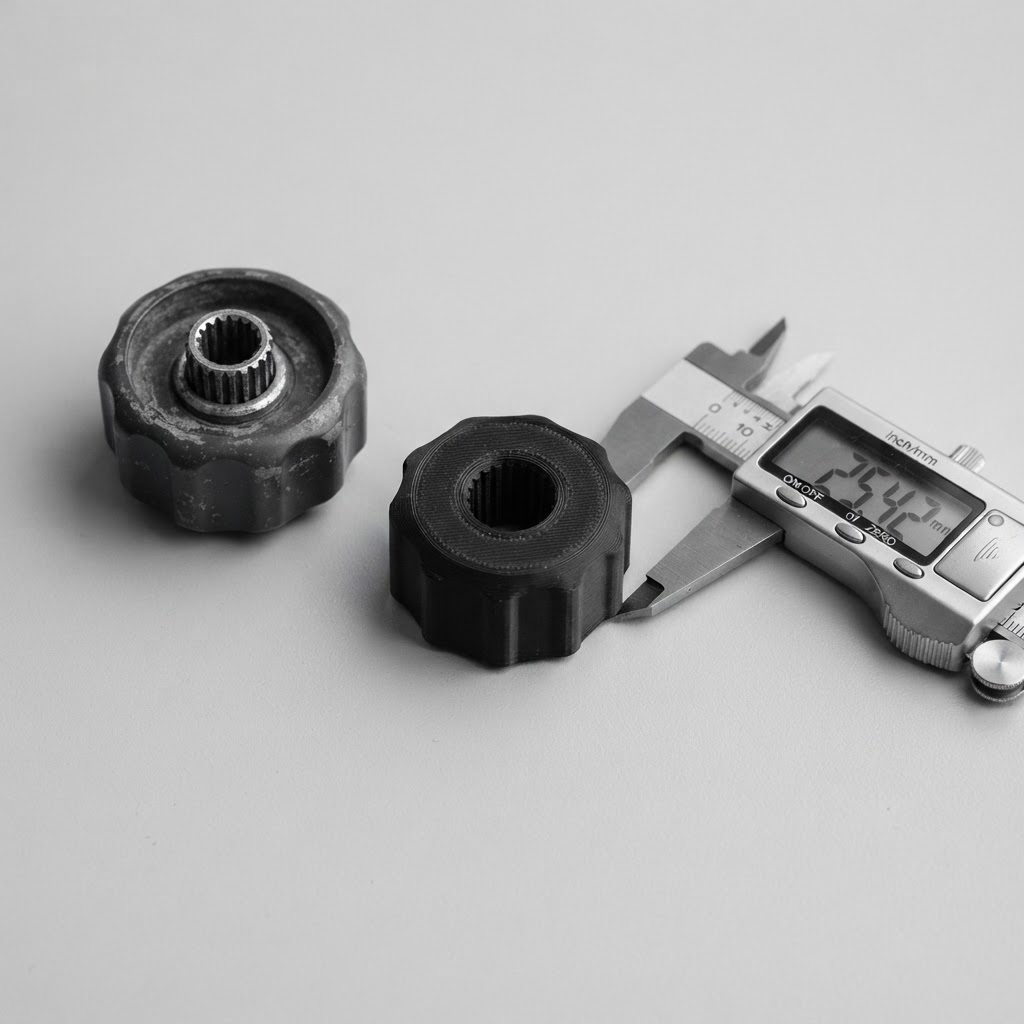
The clip that's been out of production since the Carter administration. Here's the exact loop that turns it from a missing part into one that clicks back on the shaft.
- Part
- Window knob
- Material
- PETG
- Loop time
- ~1 day
- 01
Reference
Pull the surviving knob off the good door. Caliper the splined bore, the outer diameter, and the depth. Photograph it against a scale so the CAD proportions stay honest.
- Outer diameter
- 31.4 mm
- Bore (splined)
- 8.0 mm across flats
- Overall depth
- 19.2 mm
- 02
Model
Rebuild it in CAD from the measurements. Model the splines as a slightly undersized hex so the metal shaft cuts its own seat. Keep the collar wall at 3 perimeters.
- Wall perimeters
- 3
- Bore modeled at
- 7.85 mm
- Draft on grip
- None (cosmetic)
- 03
Print
PETG in a color close to the interior. 0.20 mm layers, bore oriented vertically so the splines print clean. No supports needed if the grip faces up.
- Material
- PETG
- Layer height
- 0.20 mm
- Infill
- 40% gyroid
- 04
Test
Print just the collar-and-bore as a 6 mm coupon first. Press it onto the shaft cold. Too tight, open the bore 0.05 mm; too loose, close it 0.05 mm. Only commit to the full knob once the coupon clicks on.
- Coupon height
- 6 mm
- Adjust step
- 0.05 mm
- Target fit
- Firm press, no rock
- 05
Refine
Knock down the layer lines with 400-grit, hit it with a satin interior-trim paint, and press it home. It should read as original from the driver seat.
- Sanding
- 400-grit wet
- Finish
- Satin trim paint
- Result
- Reads as OEM
Same loop for a vent tab, a switch cap, or a trim clip. Cosmetic and non-structural only, the knob turns a window, it doesn't hold anyone in the car. Anything on the safety list stays off the print bed.
What this printer is for
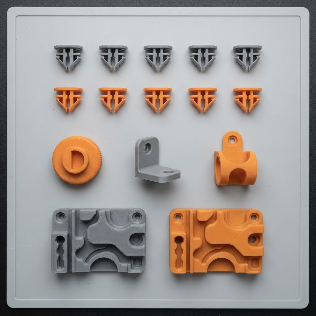
The A1 mini is excellent for small, non-structural parts where a failure means an annoyance — not an injury. Keep every project inside that line.
Great candidates
- Interior & exterior trim clips
- Knobs, dials, and switch caps
- Non-load-bearing brackets & mounts
- Cable holders, grommets, spacers
- Vent tabs & louvers (cosmetic)
- Badge & emblem backing
- Shop jigs, drilling & alignment guides
- Fit & form prototypes
Never in scope
If a part holds you in the vehicle, steers it, stops it, carries a load, or touches fuel, heat, or the engine — it is off-limits on a hobby FDM printer, full stop. The full list lives in the safety boundary.
Pick the right filament
Match the material to where the part lives. Heat is the number-one killer of hobby parts in a vehicle — a clip that survives the workshop can fail on a hot dashboard.
| Material | Best for | Nozzle temp | Heat resistance | Notes |
|---|---|---|---|---|
| PLA | Prototypes, jigs, indoor trim, mock-ups | 190–220°C | Low (~55°C) | Easiest to print, crisp detail, rigid but brittle. Softens in a hot parked car — never for anything on a sunny dash. |
| PETGRecommended | Clips, brackets, holders, exterior-ish parts | 230–250°C | Medium (~70°C) | Tougher and more heat-resistant than PLA with some flex. The default for functional restoration clips and mounts. |
| PLA-CF | Stiff jigs, dimensionally-stable fixtures | 210–230°C | Low–Med (~60°C) | Carbon-filled: stiff, matte, low-warp. Abrasive — needs a hardened nozzle. Great for guides that must hold shape. |
| ABS / ASA | Heat & UV exposure (advanced only) | 240–260°C | High (~95°C) | Best heat/UV resistance but warps badly on an open-frame A1 mini and needs strong ventilation. Not a beginner choice. |
Rule of thumb: start with PETG for functional clips and brackets, PLA for prototypes and indoor trim, and PLA-CF for jigs that must stay dimensionally stable. Always dry filament that has been open for weeks — damp filament prints weak, stringy parts.
Make it fit the first time
FDM printers do not hit exact dimensions — holes shrink, outer walls swell. Design in clearance and prove it with a test print before committing to the full part.
Clearance cheat sheet
Add this gap per side between mating parts. Start here, then fine-tune.
| Fit type | Gap / side | Typical use |
|---|---|---|
| Tight press fit | 0.10 mm | Pins, dowels, permanent joins |
| Snug / clip fit | 0.20 mm | Trim clips, snap tabs, covers |
| Sliding fit | 0.30 mm | Drawers, moving guides, lids |
| Loose / hardware | 0.40 mm | Screw clearance holes, bolts |
Test before you commit
- • Print only the mating feature as a small coupon first.
- • Print a tolerance test (0.10–0.40 mm gaps) once per new filament.
- • Dry-fit cold — parts stiffen slightly as they finish cooling.
- • Verify with calipers, not by eye.
Dial it in
Too tight? Increase the clearance by 0.05 mm. Holes reading small? Enable hole compensation in the slicer or bump the diameter 0.1–0.2 mm. Change one variable at a time and re-test.
From rough print to looks-factory
Finishing is where a home-printed part stops looking home-printed. Work through the stages in order — each one depends on the last being done well.
Deburr & clean
- Snip away support scars with flush cutters.
- Knock down the first-layer brim edge with a hobby knife.
- Wipe with isopropyl alcohol before any coating.
Sand smooth
- Start at 220 grit, then 400, then 600 wet.
- Sand in one direction to avoid swirl marks.
- For layer lines, apply filler primer, then sand again.
Prime & paint
- Two light coats of filler primer beats one heavy coat.
- Use plastic-adhesion primer on PETG and PLA-CF.
- Colour-match trim with automotive rattle-can + clear coat.
Texture & assemble
- Match factory grain with textured spray or a stipple.
- Add threaded inserts with a soldering iron for screw bosses.
- Bond PETG with two-part epoxy; superglue for PLA.
Do not print safety-critical parts. Ever.
Hobby FDM parts are not certified, not fatigue-tested, and fail without warning under heat, vibration, and load. The categories below are strictly off-limits — no exceptions, no "just this once," no temporary fixes. When a certified part fails, replace it with a proper certified part.
Braking system
Pedals, calipers, lines, clips, ABS parts
Steering
Wheel, column parts, linkage, joints
Suspension
Arms, bushings, mounts, spring seats
Fuel system
Tanks, lines, caps, filler necks, seals
Seat belts & restraints
Buckles, anchors, guides, airbag parts
Engine compartment
Under-hood parts near heat or moving belts
Structural / load-bearing
Frame, mounts, anything carrying weight
Any other safety-critical part
If failure could cause injury — do not print it
The one-question test
Before every print, ask: “If this part failed at highway speed, could anyone get hurt?” If the answer is yes, or even maybe, it belongs on a professional's bench — not your print bed. Stick to cosmetic and non-structural parts and you stay firmly on the safe side of this line.